Skip to content

brake press

Safe operation specification and maintenance system for servo press brake

Servo press brake operating system 1. The personnel of oil press should have the corresponding qualifications and must hold the certificate. It is strictly prohibited to open and use the oil press if they do not understand the machine. 2, before the class should wear the provisions of labor protection supplies. 3. Check the following items before starting: whether the photoelectric protection device is reliable, whether the travel switch is sensitive, and whether the fastener is loose. 4, remove the… Read More »Safe operation specification and maintenance system for servo press brake

Electric CNC steel tube bending machine hydraulic square tube bending machine performance characteristics:

Electric CNC steel tube bending machine hydraulic square tube bending machine performance characteristics: 1.This machine adopts PLC control, dialogue operation, simple and easy program setting. 2, can freely choose, manual, semi-automatic half-cycle, full automatic cycle function. 3, mobile foot switch, with automatic start, emergency stop, stop to continue three functions, high safety. 4, large capacity cooling circulation system, make the machine run more stable. 5. The head and elbow are exquisitely designed to provide maximum elbow space. 6, touch simple… Read More »Electric CNC steel tube bending machine hydraulic square tube bending machine performance characteristics:

Hydraulic sheet bending machine equipment is mainly composed of what parts?

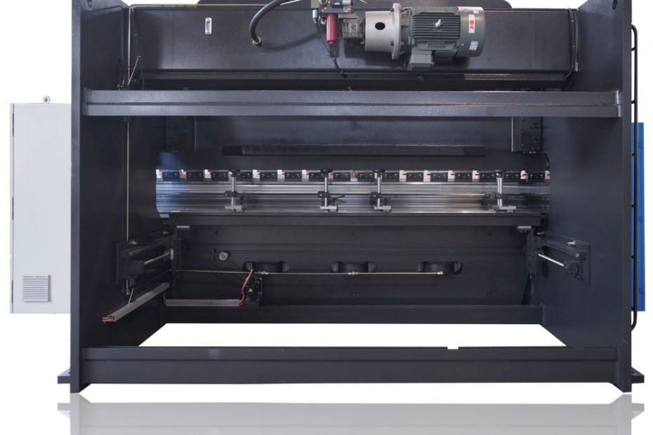
1. All steel welded structure, with sufficient strength and rigidity hydraulic sheet bending machine equipment. 2. Hydraulic upward transmission, the cylinder at both ends of the machine tool is placed on the slide block, and directly drives the sliding work. 3. Slider synchronization mechanism adopts torsional shaft to force synchronization. 4. Mechanical block structure, stable and reliable. 5. Quick adjustment of slider stroke, manual fine tuning, counter display. 6. Oblique wedge deflection compensation mechanism to ensure higher bending accuracy. The… Read More »Hydraulic sheet bending machine equipment is mainly composed of what parts?

Hydraulic sheet bending machine maintenance and daily maintenance

1) Before the maintenance or wiping of the bending machine, the upper die of the hydraulic sheet bending machine should be aligned with the lower die and then put down and shut down until the work of the bending machine is completed. If it is necessary to start up or other operations, the mode should be selected in manual and ensure safety. 2) The maintenance of the bending machine is as follows: Hydraulic system maintenance of bending machine: A. Check the… Read More »Hydraulic sheet bending machine maintenance and daily maintenance

Analysis of four common faults of hydraulic bending machine

Fault one: the hydraulic system of hydraulic bending machine has no pressure 1. Check whether the solenoid coil of the share relief valve is powered and whether the voltage of the share solenoid coil meets the requirements. For the above reasons, check the related electrical reasons. 2. Check whether the cartridge valve is stuck or the main spool is stuck, and whether the damping hole is blocked. If this is the case, remove the relief valve, clean it, and install… Read More »Analysis of four common faults of hydraulic bending machine

The importance of the structure and components of the WE67K-100T4000 bending machine

The WE67K-100T4000 bending machine  comprises a bracket, a table and a clamping plate, the table is arranged on the bracket, the table is composed of a base and a pressure plate, the base is connected with the clamping plate through a hinge, the base is composed of a shell, a coil and a cover plate, the coil is placed in the depression of the shell, the top of the depression is covered with a cover plate. When used, the wire… Read More »The importance of the structure and components of the WE67K-100T4000 bending machine

The main part and structure of WE67K CNC bending machine

Description of the main part and structure of WE67K CNC bending machine: 1, slide block part: hydraulic transmission, the slide block part is composed of slide block, oil cylinder and mechanical block fine tuning structure. The left and right cylinders are fixed on the frame, and the piston (rod) drives the slide block to move up and down through hydraulic pressure. The mechanical block is controlled and adjusted by the NUMERICAL control system. 2, the table part: operated by the… Read More »The main part and structure of WE67K CNC bending machine

DATA SHEET Numerical control for Press

CybTouch 8P is designed to control conventional press brakes with 2 axes (Y - X). As part of the CybTouch numerical controls’ family, CybTouch 8P was designed with the OEM’s needs in mind. Offering a broad range of machine functionalities in a very accessible way, it can thus be easily and precisely fine-tuned to accurately match the needs of the machine it controls. Boasting a very user-friendly touch screen interface, CybTouch 8P is a sober, practical and sensible numerical control… Read More »DATA SHEET Numerical control for Press

CNC Press Brake TP10 CNC Touch Screen Controller - User Guide

Directory 1 Overview.....................................................................................................................................3 1.1 Programming/running............................................................................................................3 1.2 More programming................................................................................................................3 1.3 Advanced parameters............................................................................................................. 4 1.4 Mode selection.......................................................................................................................5 1.5 System parameter...................................................................................................................6 1.6 Machine diagnosis................................................................................................................. 6 2.Debugging system................................................................................................................7 2.1 Valve settings.......................................................................................................................... 7 2.2 Coefficient.............................................................................................................................. 8 2.2.1 X axis....................................................................................................................................8 2.2.2 Y axis................................................................................................................................... 8 2.3 Angle Debugging.................................................................................................................... 9 2.3.1 Upper mold..........................................................................................................................9 2.3.2 Lower mold..........................................................................................................................9 2.3.3 Other parameter.................................................................................................................10 2.4 Angle calibration.................................................................................................................. 10 2.5 Length of calibration.............................................................................................................11 2.6 Frame strength......................................................................................................................12 2.7 Grid ruler.............................................................................................................................. 12 2.8 Mechanical compensation................................................................................................... 13 2.9 Great arc............................................................................................................................... 13 2.10 Y1-Y2 axis.............................................................................................................................14 3.User operation.....................................................................................................................14 3.1… Read More »CNC Press Brake TP10 CNC Touch Screen Controller - User Guide

What are the matters needing attention in the installation and debugging process of 100t hydraulic press brake mold?

1, the adjustment of the 100t hydraulic press brake , before the installation, first of all to adjust the machine performance, this process must be patient and serious, check the machine is not dust and used iron debris, etc., necessary cleaning, to reduce the trouble in the later period. 2. Adjust the stroke of the slider, pay attention to check the thickness of the mold and check whether the proportion of the upper and lower modules is normal. Normally, the… Read More »What are the matters needing attention in the installation and debugging process of 100t hydraulic press brake mold?

ru_RURussian
WeCreativez WhatsApp Support
Our customer support team is here to answer your questions. Ask us anything!
👋 Hi, how can I help?