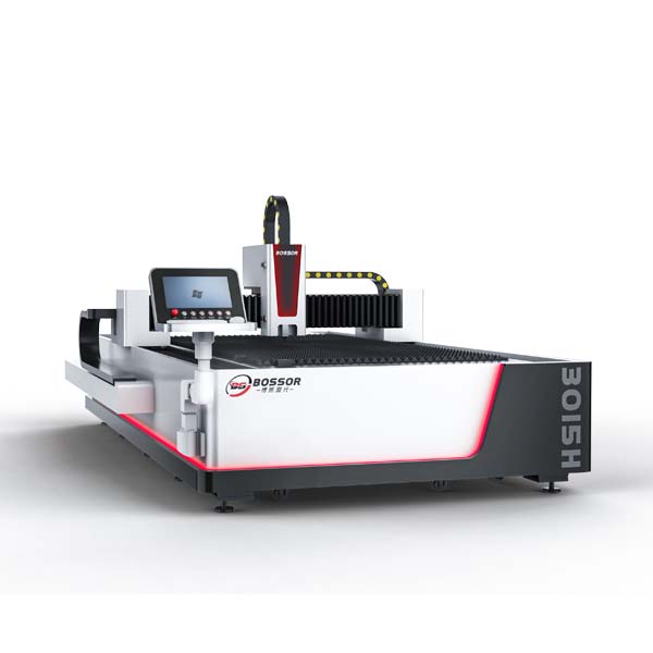
Only by properly maintaining the chuck, can the chuck accuracy last longer and the laser tube cutting machine's performance remain consistent, can we create wealth better. Here, Durmapress has prepared the chuck maintenance method for laser tube cutting machines for you! Let's take a look.
What is the chuck of laser tube cutting machine
The chuck of the laser tube cutting machine is a key component for fixing and supporting the cut tube. Its specific functions include: Precise clamping and positioning: The chuck ensures that the tube maintains a precise position during the cutting process, which is crucial for cutting accuracy. Quick response and automated operation: The pneumatic chuck achieves rapid clamping and loosening through cylinder extension and contraction. With the help of sensors and control systems, it can automatically detect when the tube is in place and perform clamping operations, reducing manual intervention and improving work efficiency. Various chuck designs: Including single chuck, double chuck and quad chuck and other different types to meet different cutting needs.
Front card maintenance details
To clean the slider, guide rod, roller, etc., you need to use a brush to clean the iron filings and dust, and then use a cleaning agent to clean the local focus. You also need to use No. 32 engine oil to refuel the oil nozzle. The maintenance cycle is once per shift.
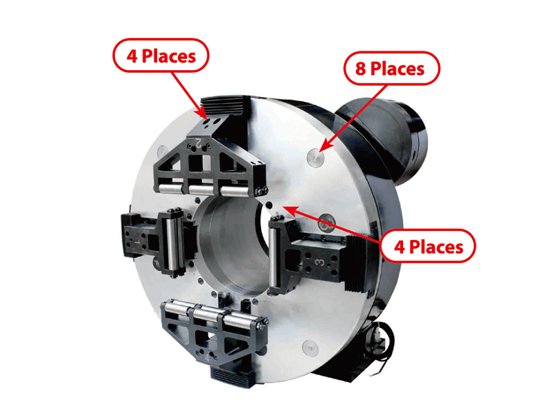
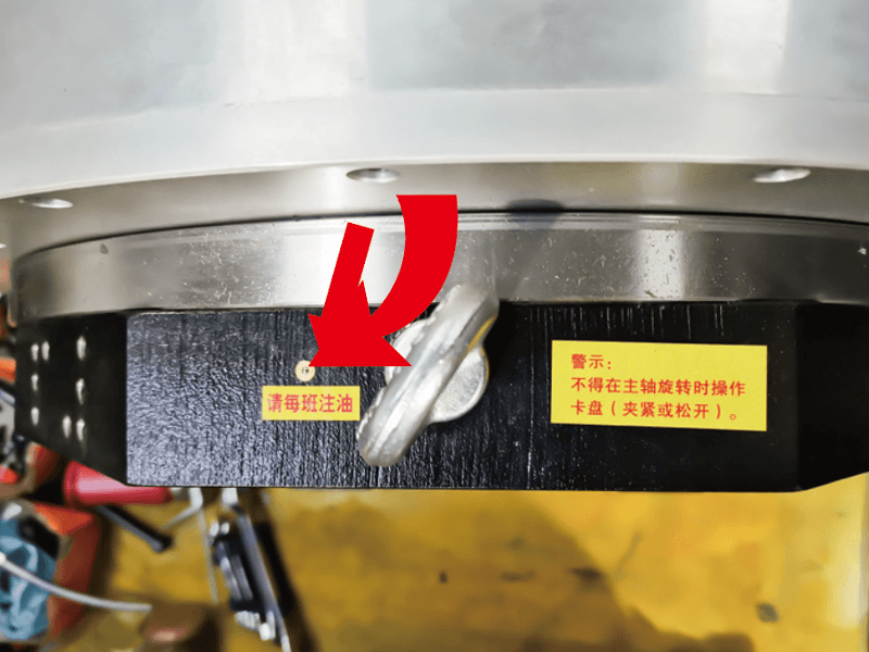
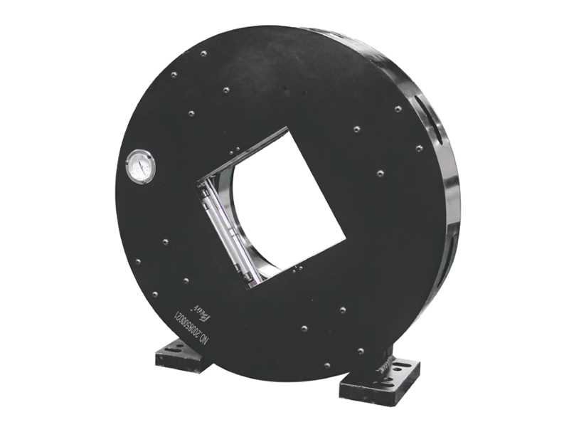

1.Full travel front card
Maintenance instructions:
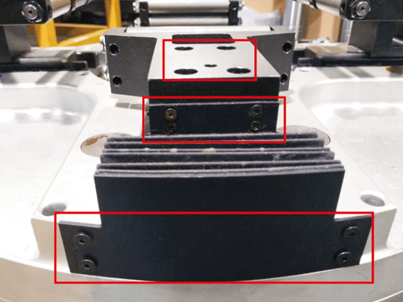
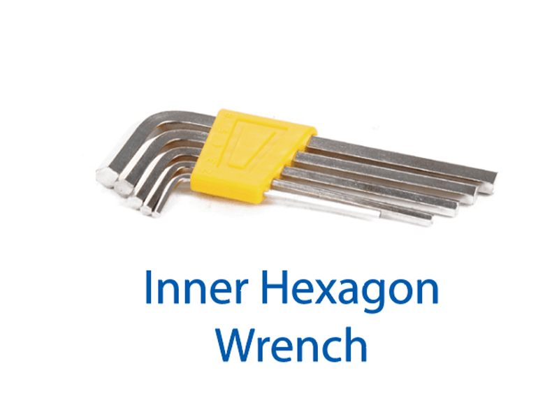
Step 1: Use an Allen wrench to remove the three screws in the box in the figure below, and then you can remove the accordion cover and roller frame. Mark them before removing them for easy installation.
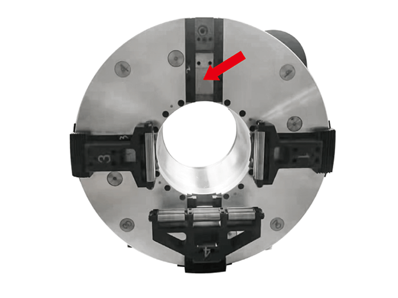
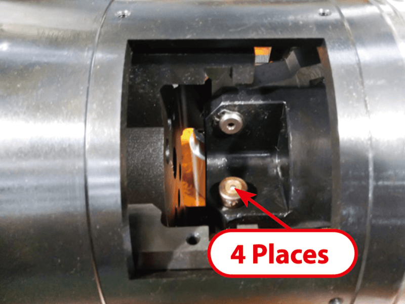
Step 2: After removal, clean the 4 power wedges with a brush and detergent as shown in the figure below. Be careful not to blow dust, iron filings and other debris into the chuck.
Step 3: After cleaning, lubricate the sliding parts and oil nozzles. Please add No. 32 or higher clean engine oil. Do not use fat oil to prevent adhesion of debris and low-temperature freezing, which may cause accidents.
Step 4: Reassemble the removed parts according to the markings, and ventilate to observe whether the action is normal.
The maintenance cycle is once every two months.

2.Simple pneumatic chuck for tube-sheet integrated machine
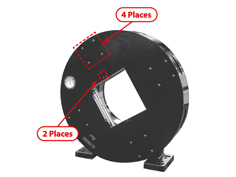
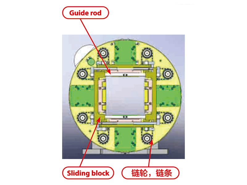
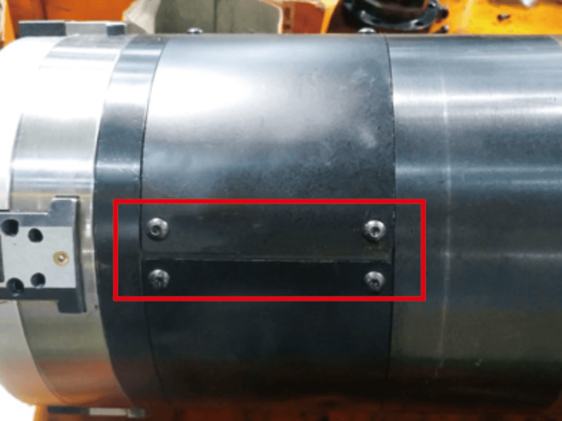
Step 1: Use an Allen wrench to remove the screws marked in the figure below, and then you can remove the dust cover. Mark it before removing it to facilitate subsequent installation.
Step 2: After removal, clean the sprocket, chain, slider, guide rod, roller, etc. with an air gun and cleaning agent as shown in the figure below.
Step 3: Ventilate and observe whether the action is normal.
Step 4: After the action is normal, install the dust cover according to the mark.
The maintenance cycle is once a month.


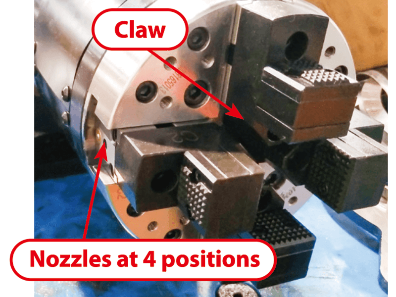
Maintenance instructions: Step 1: Clean the claws (first use a brush to preliminarily clean the iron filings and dust, then use a cleaning agent to focus on the local cleaning). Step 2: Refuel the oil nozzle (No. 32 engine oil).
The maintenance cycle is once per shift.
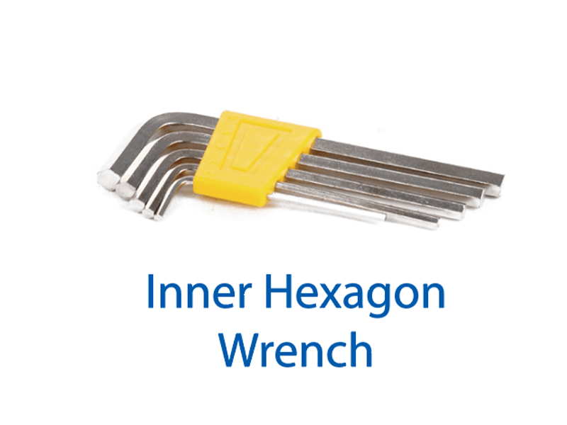
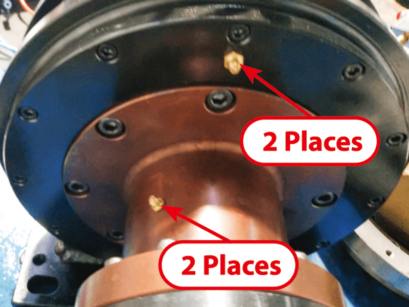

Maintenance instructions: Step 1: Use an Allen wrench to remove the 4 screws shown in the figure below, then you can remove the 4 dust covers (mark them before removing).
Step 2: After removal, use an air gun and cleaning agent to clean the inside as shown in the figure below.
Step 3: Refuel the active parts and oil nozzle (No. 32 engine oil). Ventilate and observe whether the action is normal. If it is normal, install the dust cover according to the mark.
The maintenance cycle is once every two months.


3.Maintenance precautions
The first point is to shut down the machine before maintenance, cut off the power and gas, and do not start the chuck to prevent safety accidents.
The second point is to refuel and maintain according to the instructions at the refueling point if the refueling point is not specified.
The third point is to regularly refuel the oil tank of the triplex and control the oil dripping speed.
Instructions for replacing wearing parts
1.Simple pneumatic chuck roller frame disassembly of tube-sheet integrated machine
First, ventilate the chuck to the clamping state, remove the screws with an Allen wrench as shown in the figure below, and remove the dust cover.
Then, remove the screws with an Allen wrench as shown in the figure below to remove the roller frame. Remove the 4 roller frames in total according to the positions shown in the figure.
2.Full stroke front card roller frame disassembly
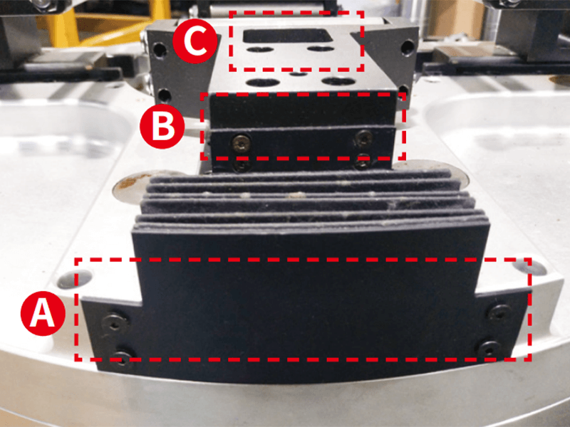
Step 1: Remove the screws at A and B as shown in the figure below and remove the bellows cover.
Step 2: Use an Allen wrench to remove the screws at C, and then you can remove the roller frame (all four roller frames should be removed in this order).
3.Roller replacement
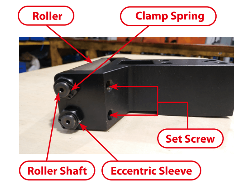
Disassembly: Step 1, loosen the set screw with an Allen wrench as shown in the figure below.
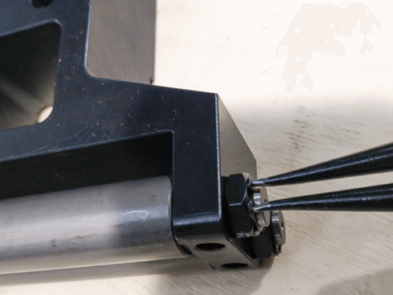
Step 2, remove the circlip with circlip pliers.
Step 3, gently knock down the roller shaft from one side with a copper rod, and remove the eccentric sleeve and clean it for use.
Assembly:
Step 1, mark the highest point of the eccentric sleeve with white.
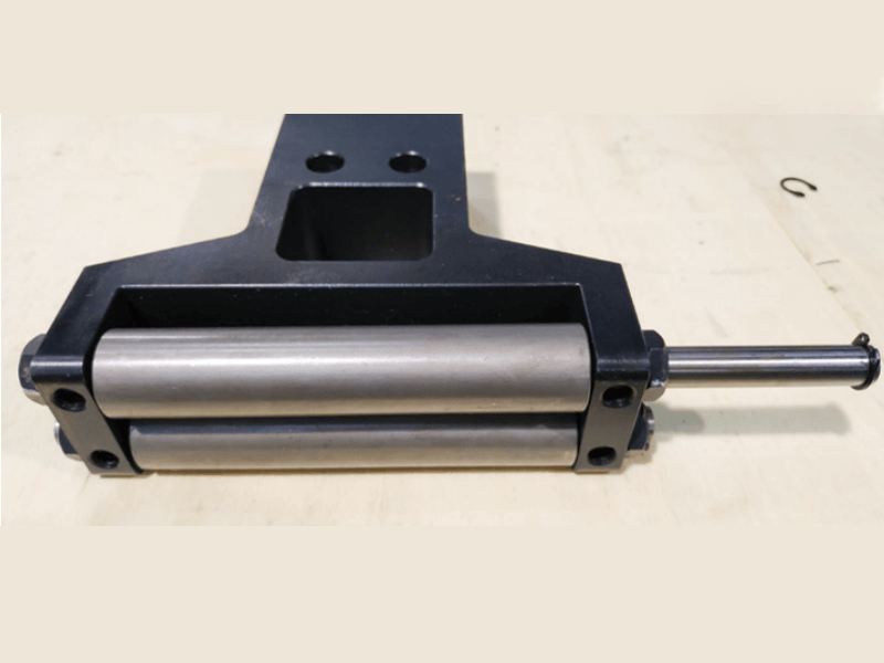
Step 2, place the roller with the bearing installed in the slot of the roller frame and concentric with the shaft hole of the roller frame. At this time, insert the roller shaft from one side and gently tap the roller shaft with a copper rod until one end of the roller shaft exceeds one side of the roller frame.
Step 3, install the eccentric sleeve on both sides of the roller frame, ensuring that the high point direction of the eccentric sleeve on both sides is consistent and facing outward.
Step 4, adjust the position of the roller shaft, install the circlips at both ends, lightly tighten the set screws, do not tighten them, install the roller frame on the chuck and adjust the accuracy before tightening.
4.Tail clamp claw replacement
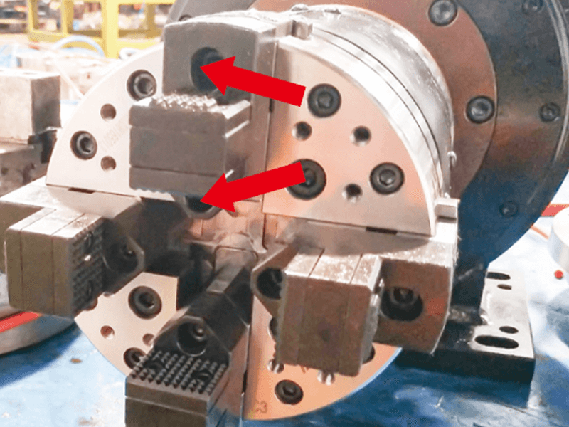
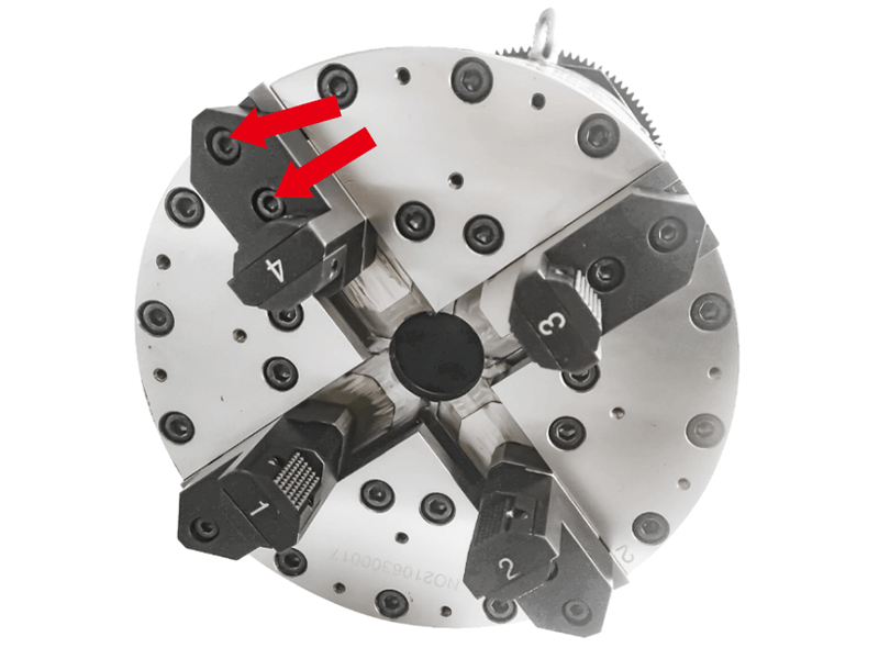
The first step is to remove the two screws with an Allen wrench as shown in the figure below to remove the claws. The four claws in total are removed in the same way.
The second step is to replace the prepared claws with another pair of claws, pay attention to the keyway position, and tighten the two screws. The accuracy of the claws can be fine-tuned by the screws on the power wedge.
About Us
Durmapress specializes in designing, manufacturing and selling various metal processing equipment, including bending machines, shears, punches, laser cutting machines, etc. The company was founded in 2000. With years of experience and technology accumulation. DurmaPress has become one of the well-known brands in China's metal processing machinery industry.
Contact Us
Recent Posts
Categories
Follow Us
Weekly New Video
Contact us for more information
If you have any information about our products, please contact us and we will reply within 24 hours.

-300x169.jpg)

