In this part, we will introduce in detail the application fields of CNC hydraulic press brake in modern industrial production and its importance. As a key mechanical equipment in the field of metal processing, CNC hydraulic press brake is widely used in the processes of bending, forming and processing of metal plates. Its precise processing performance, high efficiency and stable machine performance make it play an irreplaceable role in aviation, automotive, construction, home appliance and other industries. In addition, we will also deeply analyze the basic composition of the hydraulic system and its function in order to provide the necessary theoretical basis for the subsequent troubleshooting. Hydraulic system is mainly composed of hydraulic pumps, control valves, actuators, tanks, pipelines and hydraulic oil. Its main function is to transfer energy through the pressure oil to realize the power drive and control of various mechanical equipment.
Detailed expansion of the fault description
Detailed description of the fault phenomenon: in the process of mechanical processing, the slider in the work in the phase of the pressure phenomenon, resulting in its inability to successfully complete the scheduled bending operation tasks. The occurrence of this phenomenon, seriously affecting the production efficiency and product quality, urgent need for fault analysis and troubleshooting.
The working stages of the hydraulic system are described in detail
- fast-forward stage: in this stage, the hydraulic system will quickly provide pressure to the slide, so that it is fast forward in order to quickly reach the position of the workpiece, in preparation for the next phase of the work into the stage.
- work into the stage: in this stage, the hydraulic system needs to provide continuous and stable pressure to the slide to ensure that the slide can be at the appropriate speed and force to carry out the processing of the workpiece, such as bending operations.
- rapid return phase: after the completion of the workpiece processing, the hydraulic system will quickly reduce the pressure, so that the ram quickly return to the next round of processing.
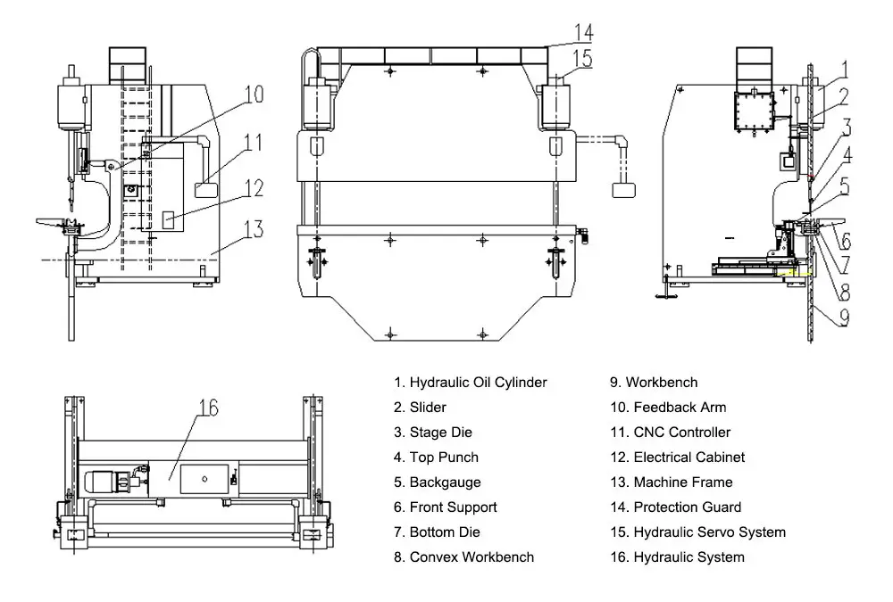
Detailed overview of the hydraulic system and its working principle diagram and key components analysis
Hydraulic system is a mechanical transmission system that utilizes liquid as the working medium and transfers energy through pressure. It is mainly composed of hydraulic pumps, control valves, actuators, auxiliary devices and hydraulic oil five major components. The working principle of the hydraulic system is the use of hydraulic pumps to transport hydraulic oil from the low-pressure region to the high-pressure region, and then through the control valve to control the flow of hydraulic oil and pressure, drive the actuator to complete a variety of mechanical movements. Hydraulic system is characterized by stable output power, high control accuracy, fast response speed and good reliability, and is widely used in various engineering machinery, industrial equipment and automated production lines and other fields.
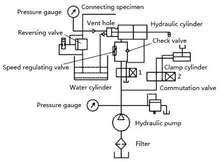
Hydraulic system schematic diagram is a description of the components of the hydraulic system and its connection relationship graphic representation, which mainly includes hydraulic pumps, control valves, actuators, pressure sensors, flow meters and other components. Hydraulic system schematic diagram helps us to understand the working principle of the hydraulic system and the function of each component, and provides an important reference for us to design and maintain the hydraulic system.
The main components of a hydraulic system are hydraulic pumps, control valves, actuators, pressure sensors, flow meters and so on. Among them, the hydraulic pump is the power source of the hydraulic system, used to transport hydraulic oil from the low-pressure area to the high-pressure area; control valves are used to control the flow of hydraulic oil and pressure, thereby controlling the movement of the actuator; actuators are the execution parts of the hydraulic system, used to complete a variety of mechanical movements; pressure sensors and flow meters are used to monitor the pressure and flow of the hydraulic system, providing feedback signals for the control system.
Solenoid valve is an important part of the hydraulic system, its action sequence has a great impact on the working effect of the hydraulic system. The action sequence of the solenoid valve is usually programmed and controlled by the control system according to the actual demand, to ensure that the hydraulic system can work in accordance with the predetermined order and method. The action sequence of the solenoid valve mainly includes the energizing and de-energizing sequence of the solenoid valve, as well as the switching sequence of the control valve connected to it. By reasonably setting the action sequence of the solenoid valve, the hydraulic system can realize complex action control to meet various engineering needs.
Failure analysis and troubleshooting
Failure analysis and troubleshooting is to ensure the normal operation of machinery and equipment is an important link, through the possible causes of failure to carry out detailed analysis and investigation, you can quickly locate the problem and take appropriate measures to deal with it. Common causes of failure include failure of the solenoid of the proportional relief valve, wear and tear or seal failure of the cartridge valve, and failure of the liquid filling valve.
In order to ensure the accuracy of fault troubleshooting, certain steps need to be followed. First, check whether the solenoid of the proportional relief valve is normally energized, if the solenoid is not energized, then the proportional relief valve cannot work normally. Second, check the wear of the cartridge valve 2. If the cartridge valve is badly worn or the seal fails, it will cause the pressure of the system to be unstable. Finally, check the state of the liquid filling valve, if the liquid filling valve is faulty, it may lead to insufficient pressure in the system.
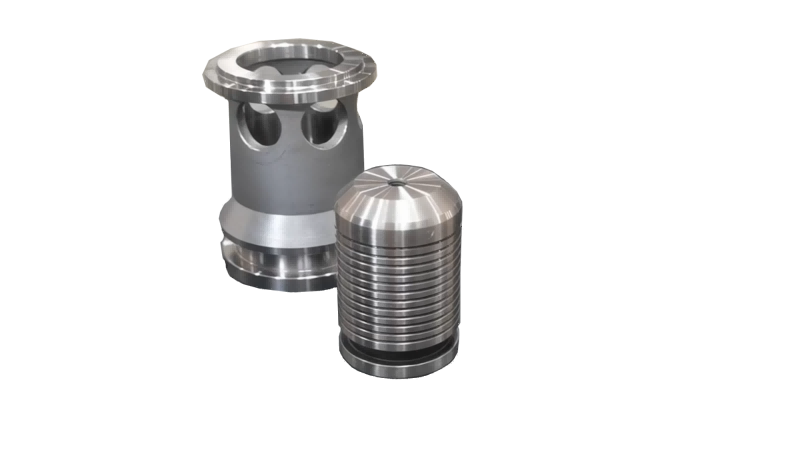
In the actual troubleshooting process, we found that the liquid filling valve spool damage is the main cause of insufficient pressure. To solve this problem, we need to modify the liquid filling valve or customize and purchase a new liquid filling valve. The working principle of the liquid filling valve is that when the slider moves down quickly, the pilot valve opens and the liquid enters the working cylinder, and when the slider moves up quickly, the pilot valve closes and the liquid in the working cylinder is compressed, thus generating pressure.
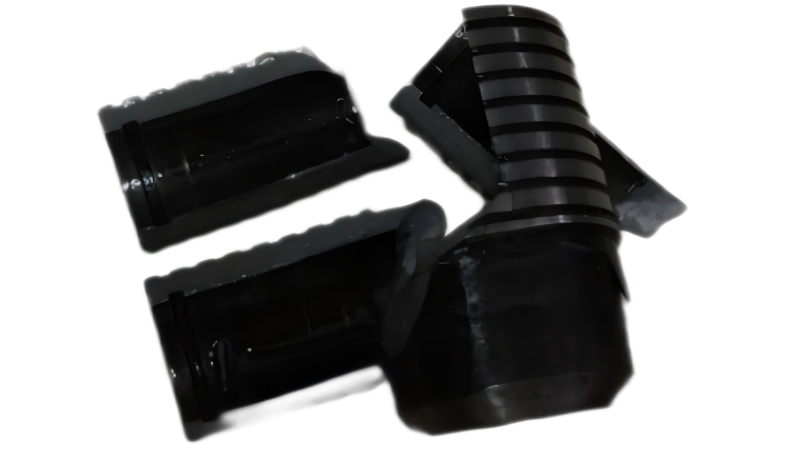
During the troubleshooting process, we customized and procured a new liquid filling valve and solved the interface mismatch. At the same time, we retrofitted the pilot valve top rod and lengthened the length of the top rod to ensure that the liquid filling valve could work properly. Before and after the modification, we compared the structural design of the top bar to ensure that the modified top bar could meet the work requirements.
After installing the new charging valve and conducting test runs, we checked the effectiveness of the troubleshooting. Through the above remodeling and troubleshooting, the pressure stability of the equipment was greatly improved and the fault was effectively solved.
Summarize
In this troubleshooting process, we came up with the basic steps and methods of hydraulic troubleshooting, and also compared the advantages and disadvantages of self-modification and customized procurement. We suggest that in the future, we should pay more attention to the maintenance and upkeep of the equipment and carry out regular troubleshooting to minimize the occurrence of failures. At the same time, for similar faults, we should choose the appropriate treatment method according to the specific situation to ensure the normal operation of the equipment.
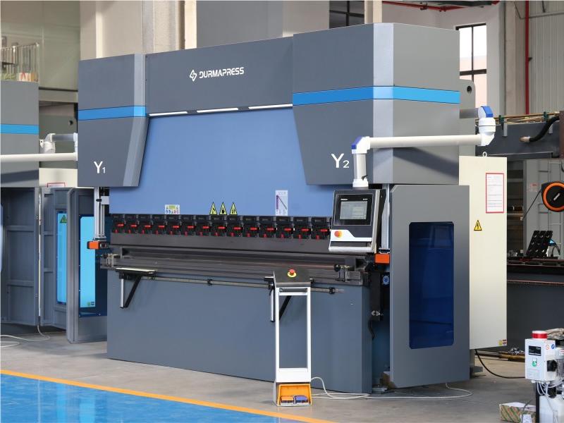
About Us
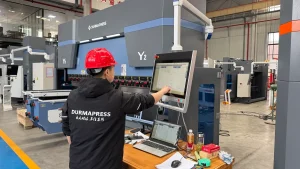
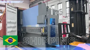
Durmapress specializes in designing, manufacturing and selling various metal processing equipment, including bending machines, shears, punches, laser cutting machines, etc. The company was founded in 2000. With years of experience and technology accumulation. DurmaPress has become one of the well-known brands in China's metal processing machinery industry.


Contact Us
Recent Posts

Categories
Follow Us
Contact us for more information
If you have any information about our products, please contact us and we will reply within 24 hours.