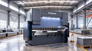
Press Brake working principle
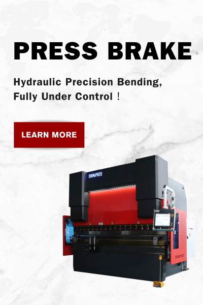
The press brake realizes the precise bending of the material through bending mechanics, using precise mechanical and hydraulic systems to accomplish this process. During the bending process, the material is held in a mold, while a ram is hydraulically or electrically driven to move along the space between the upper and lower molds. This movement process applies a bending force to the material, causing it to bend into the desired shape within the mold. By adjusting the stroke, speed, and pressure of the ram, the operator can control the degree and precision of bending of the material to meet a wide variety of bending needs. The precision and controllability of this principle of operation make the press brake an ideal tool for processing parts of different shapes and sizes.
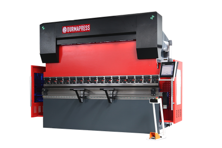
Classification of Bending Machines
Bending machines can be categorized into various types according to different ways of classification. According to the transmission can be divided into mechanical transmission and hydraulic transmission; according to the shape of the slide can be divided into crank linkage, elbow and no elbow; according to the type of table can be divided into offset, upward and downward dynamic type. Different types of bending machines have different characteristics and scope of use, and should be selected according to the actual needs.
Base device
Cylinder
Piston: the core component of the hydraulic system
In a press brake system, the piston is a sealed cylinder part located inside the hydraulic cylinder, which realizes up and down movement through the push of liquid. The main role of the piston is to convert hydraulic energy into mechanical energy to push other parts to work. The piston is made of high-strength materials to ensure good pressure resistance in high-pressure environments.
Piston rod: bridge between piston and ram
The piston rod is the part that connects the piston to the ram and transmits the movement of the piston to the ram. The design of the piston rod requires sufficient strength and stability to withstand the high-pressure fluid impacts in a press brake system. Through the connection of the piston rod, the piston and the ram can work in tandem to realize processes such as bending of workpieces.
Cylinder barrel: the solid shell of the hydraulic cylinder
The cylinder barrel is the external structure that surrounds the piston, which is a housing that is subjected to pressure. Cylinder barrels are usually made of strong materials, such as steel and aluminum, to ensure that no deformation occurs in a high-pressure environment. The role of the cylinder barrel is to withstand the pressure of the hydraulic fluid and provide a track for the piston to move.
Seals: the key to guaranteeing the sealing of the hydraulic system
Seals are installed inside the hydraulic cylinder, and their main function is to prevent fluid leakage while ensuring that pressure is maintained during piston movement. The material and design of the seals are required to maintain good sealing performance in harsh environments such as high pressure and high temperature.
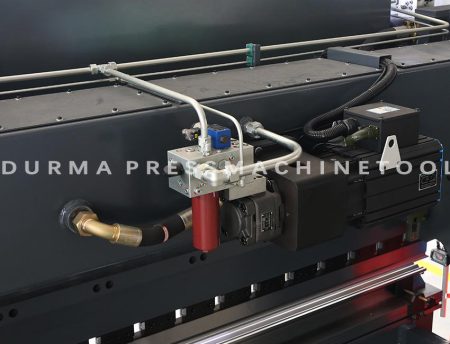
Hydraulic interface: the channel connecting the hydraulic pipeline
Hydraulic interface is the connection between the hydraulic cylinder and hydraulic piping components. Through this interface, the hydraulic fluid can enter and leave the hydraulic cylinder. The design of the hydraulic interface requires good sealing performance to prevent hydraulic oil leakage.
Principle of operation: the circular flow of hydraulic fluid supply
Hydraulic oil enters the side of the hydraulic cylinder through the hydraulic line, is applied to the piston, and pushes the piston upward. This process is the chemical energy of the hydraulic fluid into the mechanical energy of the piston.
Push the piston rod
The movement of the piston is transmitted to the ram through the piston rod, causing the ram to move up and down. This process is to convert the chemical energy of the hydraulic fluid into the mechanical energy of the slide, thus completing the workpiece bending and other processes.

Liquid return
After working, the hydraulic oil flows through the hydraulic cylinder hydraulic interface back to the hydraulic system to complete a work cycle. This process is to discharge the hydraulic fluid from the hydraulic cylinder after work, preparing the conditions for the next work cycle.
In short, the press brake system, through the concerted efforts of the piston, piston rod, cylinder, seals, and hydraulic interface, realizes the circulating flow of hydraulic oil, converting the chemical energy of the hydraulic oil into mechanical energy to complete a variety of processes. The design and material selection of these components are based on the working principle and actual needs of the press brake system to ensure the stability and reliability of the system under various working conditions.
Fixture
A fixture is a device used to hold a workpiece and keep it in a desired position. In a press brake, the design of the fixture directly affects the positioning and stability of the workpiece. Common types of fixtures include:
Bottom Die Fixture
Mounted on the base of the press brake, it is used to clamp the lower part of the workpiece to ensure that the workpiece is stable and does not move.
Top Mold Fixture
Mounted on the slide of the press brake, used to clamp the upper part of the workpiece, to ensure that the workpiece in the bending process maintains the correct position.
Side Die Clamps
Mounted on the side of the press brake, these clamp the side of the workpiece to provide additional support and positioning.
Sliders
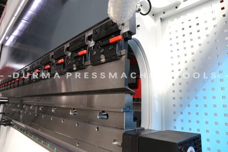
The slide is the part of the press brake that moves up and down, usually controlled by a hydraulic or mechanical system. The slider is fitted with an ejector clamp that applies force to bend the workpiece by moving it up and down. The design and performance of the slide have a significant impact on the accuracy and efficiency of the bending process.
Slide guidance system
To ensure that the slide in the up and down movement maintains smoothness, usually using high-precision guide rails and guides.
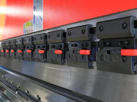
Slider transmission system
Through the hydraulic cylinder, screw drive, etc., to control the up and down movement of the slider, to provide sufficient power and speed.
Slider Adjustment System
Allows the position and angle of the slider to be fine-tuned to suit the bending needs of different workpieces.
Backstop
The backstop, as a key device, plays a vital role in the bending and forming process. Its main function is to control the positioning of the material to ensure that the material can be deformed precisely according to the predetermined trajectory and angle during the bending process. The precision and adjustment ability of the backstop have a direct impact on the quality of the bending and forming.
In practice, we need to make timely adjustments according to different material specifications and dimensions to ensure the precision of bending molding. This is because different materials in the process of bending require different strength and angles. If the parameters of the backstop are not set properly, it may lead to material offset, deformation, and so on, thus affecting the quality of bending molding.
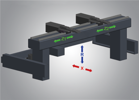
In short, as a key device to control the positioning of the material, the accuracy and adjustment of the backstop are of great significance to the bending molding. In the process of use, we should pay full attention to the accuracy and adjustment ability of the rear stopper, according to different material specifications and sizes, to make timely adjustments to ensure the quality of bending molding. At the same time, it is also necessary to regularly check and maintain the backstop to ensure its normal operation, thereby improving the efficiency and accuracy of the entire press brake and forming process.
Caja eléctrica
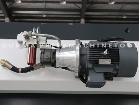
The main function of the electrical box is to integrate the electrical wiring, measuring instruments, switches, and other related equipment of the press brake in a metal cabinet to realize the centralized management of the electrical system of the press brake to ensure the stable operation of the electrical part.
Pedal
It integrates the functions of emergency stop, cycle, and single remote control in the press brake, and is one of the four main bodies of the press brake operation. The foot pedal allows you to freely control the left and right movement of the stop finger, turn the machine on and off, and also integrates the function of controlling the machine tool and so on. In addition, the foot pedal also has the ability to add the WIFI module to realize the networking function and realize the monitoring and management of the whole area without any gap, which makes the operation easier and more efficient.
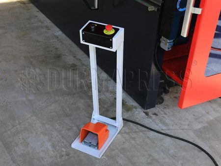
In practice, the foot pedal can improve operational efficiency and safety. The operator can quickly control the movement of the blocking finger and the switch of the machine through the foot pedal, realizing fast and accurate processing operation. At the same time, the emergency stop function of the foot pedal can quickly stop the operation of the machine in case of emergency, protecting the safety of the operator and the equipment. In addition, through the installation of a WIFI module, remote control, and management can be realized, which is convenient for the automation and intelligent management of the production line.
High-end Options
Control Numerical System
ESA
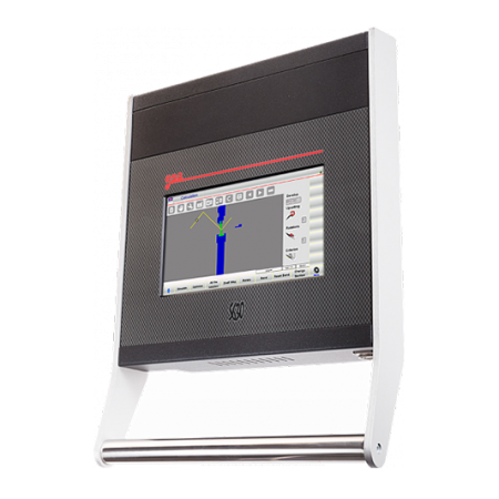
Take ESA-S630 as an example; it is the representative work of ESA in the CNC system of a press brake. It has (4+1) axis control and customization capability, a standard 10" color touch screen, supports data and graphic programming, automatic calculation of the press brake process, and anti-collision. Powerful calculation functions include unfolding length calculation, mold library graphic, and press brake pressure calculation. The system is rich in auxiliary functions and supports hardware configuration modification and a variety of communication interfaces. The comprehensive and powerful performance makes ESA-S630 highly acclaimed in the market and become the leader in the field of CNC control systems for press brakes.
DELEM
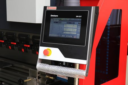
Founded in 1978 in the Netherlands, Delem is a leading company specializing in CNC for sheet metal manufacturing. Delem's press brake control systems include the DA-Retrofit program, DA-40 series, DA-50 series, and DA-60 series. The DA-66T, 69T, 53T, 58T, 41T, and 42T of Delem CNC controls are touch screen versions.
CYBELEC CNC
Cybelec's CNCs offer a wide range of options, including push-button versions (e.g., CT8P, CT8PS, CT15P) and touch-screen versions (VisiTouch series). The push-button version is for those who prefer a more traditional control method, offering a physical push-button interface. The touch screen version features a modern streamlined glass surface touch screen with a user-friendly interface that allows users to wear gloves for improved ease of operation.
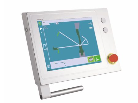
These CNCs are equipped with the Cybtouch tool, which enables wireless transmission between the PC and the system, providing users with greater flexibility in operation and control. Touch screen features include 2D or 3D graphical programming, allowing users to program directly, while features such as automatic calculation of press brake sequences, angle measurement, and collision detection improve operational efficiency and accuracy.
In addition, Cybelec's CNCs have multi-axis motion control capabilities, making them suitable for a number of applications that require tandem press brake machines. Taken together, Cybelec's CNCs provide users with a comprehensive control solution for different press brake applications through diverse versions and advanced features.
Compensation system
In industrial production, the press brake process is an important metal processing technology that enables sheet metal to be deformed to a predetermined shape and size without destroying its original properties. However, in the press brake process, due to the influence of various factors, it often leads to the deviation of the shape and size of the workpiece. In order to solve this problem, compensation systems have emerged. There are three main types of compensation systems: angular compensation, length compensation, and gap error compensation.
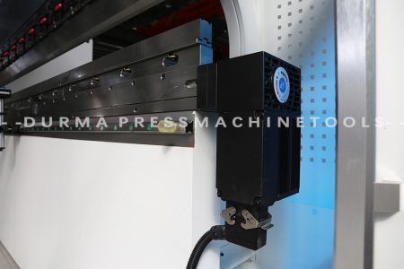
Angular Compensation
During the press brake process, the slider may produce angular deformation for various reasons, which will directly affect the bending angle of the workpiece. In order to solve this problem, the compensation system will monitor the angular deformation of the slider in real time and adjust the control parameters to produce the desired bending angle of the workpiece during the bending process. In this way, even if the angular deformation of the slider occurs, it can ensure that the bending angle of the workpiece meets the design requirements.
Length Compensation
In the process of metal plate bending on a press brake, the material will undergo expansion and contraction forces, leading to changes in the length of the workpiece. To ensure that the final size of the workpiece meets the design requirements, the compensation system will adjust the length compensation parameters in real time according to the expansion and contraction of the material in the bending process. This way, the length of the workpiece can be effectively controlled even if the material is deformed.
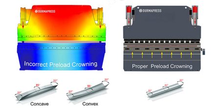
Gap Error Compensation
In the various mechanical connection parts of the press brake, there may be some tiny gaps due to the machining accuracy of the parts, assembly errors, and other factors. These gaps will impact the machining accuracy of the workpiece and therefore need to be compensated. The compensation system will eliminate these errors by real-time monitoring of the gap situation in the mechanical connection part, thus improving machining accuracy.
Sistema hidráulico
The hydraulic system is an important and indispensable part of modern mechanical equipment, providing powerful power for various equipment by converting liquid energy into mechanical energy. Below, we will introduce the main components of the hydraulic system in detail, in order to better understand its working principle and function.
Hydraulic Pump
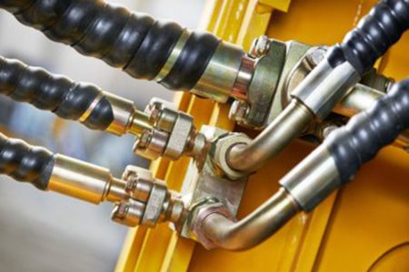
The hydraulic pump is the core component of the hydraulic system, responsible for generating and supplying the liquid pressure required by the hydraulic system. Common hydraulic pumps include piston pumps and gear pumps. Plunger pumps have the advantages of a compact structure, high efficiency, and strong anti-pollution ability, suitable for high-pressure, high-flow applications. Gear pumps, on the other hand, are widely used in low-pressure, low-flow applications due to their simple structure and easy maintenance.
Cilindro hidráulico
The hydraulic cylinder is the key component that converts the energy of the liquid into mechanical energy, pushing various parts of the press brake machine into motion. In the press brake and other equipment, the hydraulic cylinder is responsible for controlling the up and down movement of the slider, achieving accurate positioning and effective control of the working parts.
Hydraulic Valves
Hydraulic valves are key components that control the flow direction, flow rate, and pressure of the liquid. In equipment such as press brakes, hydraulic valves are used to control the flow of liquid into and out of the hydraulic cylinder, thus realizing the movement of the ram. There are many types of hydraulic valves, including check valves, flow control valves, pressure control valves, etc., each responsible for different control functions.
Hydraulic Tank
The hydraulic tank is an important component for storing hydraulic fluid, maintaining the fluid level and temperature of the system. At the same time, the hydraulic tank also prevents hydraulic oil overheating through the cooling system, ensuring that the system works properly in a high-temperature environment.
Hydraulic Piping
Hydraulic piping connects hydraulic pumps, hydraulic cylinders, hydraulic valves, and other components to transfer liquid energy. Hydraulic piping in the system plays a bridging role, serving as the channel of liquid flow. To ensure the normal operation of the hydraulic system, the hydraulic pipeline needs to have sufficient strength and sealing performance to prevent liquid leakage.
In summary, hydraulic pumps, hydraulic cylinders, hydraulic valves, hydraulic tanks, and hydraulic lines, among other components, together constitute a hydraulic system. They each play their own role and work together to provide powerful power for various machinery and equipment.
Principio de funcionamiento
The working principle of the hydraulic system can be divided into four main parts: pressure generation, control valve operation, hydraulic cylinder movement, and hydraulic oil return. First, the hydraulic pump increases the liquid pressure to form a high-pressure fluid. This process is achieved by compressing the fluid to provide the necessary pressure support for subsequent operations.
Pressure Control
Next, the control valve operates in response to a control signal to adjust the flow direction, flow rate, and pressure of the fluid. This process is realized by opening and closing the hydraulic valve. There are many types of hydraulic valves, and you can choose the right valve according to actual needs to meet the requirements of various working conditions.
Hydraulic Cylinder Movement
High-pressure fluid enters the hydraulic cylinder through the hydraulic pipeline to push the slide up and down. This process converts hydraulic cylinder pressure energy into mechanical energy, completing the workpiece bending and other actions through the up and down movement of the slider. The design and manufacturing precision of the hydraulic cylinder directly affect the performance and life of the hydraulic system.
Hydraulic Oil Return
Finally, the used hydraulic oil is returned to the hydraulic tank through the hydraulic pipeline. This process is realized through the suction effect of the hydraulic pump and the connectivity of the tank. The returned hydraulic fluid is leveled and temperature balanced in the tank to ensure the proper operation of the hydraulic system.
According to different application requirements, different configurations can be selected to improve productivity and reduce costs. For example, the multi-station device can allow one press brake machine to carry out multiple processes simultaneously, improving production efficiency. A quick mold change device can complete the replacement of molds in a short period, reducing production costs. All these configurations can be optional according to actual demand, allowing the hydraulic system to better serve the production process.
Y-axis Control Method
In a press brake, the Y-axis is typically the axis that controls the up and down movement of the slider. The way the Y-axis is controlled is crucial for the accuracy and efficiency of the operation of the press brake. The following are some common Y-axis control methods:
Conventional Hydraulic Control
In a traditional hydraulic press brake, Y-axis control is mainly realized through the hydraulic system. The hydraulic cylinder is responsible for controlling the up and down movement of the ram, and precise control of the Y-axis is achieved by adjusting the fluid flow and pressure in the hydraulic system. This method is still widely used in many press brakes, especially in small and medium-sized machines. The advantage of traditional hydraulic control is its high stability, making it suitable for a wide range of bending operations. However, its response speed and positioning accuracy are relatively low and cannot meet the demand for high-precision bending.
Electric Control
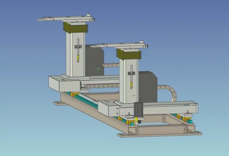
With technological advancements, some advanced press brakes have begun to use electric control. In this method, the motor directly drives the movement of the Y-axis. Electric control typically uses servo motors or stepping motors to achieve accurate control of the Y-axis through a sophisticated electronic control system. The electric control method has the advantages of fast response speed and high positioning accuracy, especially suitable for workpieces that require high-precision bending. However, electric control has higher requirements for power supply stability and the equipment operating environment, potentially leading to increased equipment costs.
Hybrid Hydraulic and Electric Control
To fully leverage the advantages of hydraulic and electric control, some press brakes use hybrid control. This involves incorporating electric control on the basis of the hydraulic system to realize Y-axis control. This approach combines the stability of traditional hydraulic control with the precision of electric control, suitable for applications requiring higher bending accuracy. The hybrid control method improves bending accuracy and reduces equipment costs, offering better cost performance.
Common Problems and Solutions
After data research and customer feedback, common problems generally include the main motor not starting, the slider not descending rapidly, the slider being unable to enter the bending position or having a very slow bending speed, the main motor automatically stopping, any valve getting stuck, and the cylinder sliding down slowly. The following will dismantle each issue one by one.
The main motor can not start
Causes
- Press brake starting circuit failure, such as: failure to release the emergency stop button, loose cable wiring, 24V control power supply issues;
- Components related to the press brake starting part failure, such as: thermal relay, circuit breaker, AC contactor overload protection, or damage to these components;
- Power supply problems.
Measures
- Check the press brake starting circuit for issues like the emergency stop not being released, loose wiring, or problems with the 24V control power;
- Examine the components of the press brake starting circuit for overload protection. If an issue is identified, analyze the reasons and check whether the components are damaged;
- Verify the normalcy of the three-phase power supply.
The slider cannot move down rapidly
Causes
- The press brake guide for the slider is adjusted too tightly;
- The rear blocking material axis is not in the correct position;
- The slider is not on the dead center position;
- Foot switch and other signals are not entering the module;
- Proportional servo valve is faulty.
Measures
- Check whether the press brake guide for the slider is appropriately adjusted;
- Verify the presence of a cursor at the actual position of X on the system, or check whether the programmed value of the rear blocking axis matches the actual value in the manual interface;
- Ensure that the status of the Y-axis on the system is "1." If it is "6," check the actual coordinates of the Y-axis, and the value should be less than the difference between the Y-axis and return;
- Inspect foot switch and other input signals for normal operation according to the electrical schematic diagram;
- Check whether the feedback from the proportional servo valve is normal.
Slider cannot perform bending or bending speed is very slow
Causes
- The press brake slider has not reached the speed conversion point;
- Inadequate parameter settings in the system Y-axis bending section;
- Insufficient pressure due to programming operation issues, machine parameter setting problems, or hydraulic reasons.
Measures
- Check if the Y-axis state transitions from "2" to "3". The actual value of the Y-axis should exceed the speed conversion point value. If not, adjust the parameters of the fast-forward part;
- Re-adjust the parameters in the Y-axis bending section;
- Investigate whether the issue lies in programming, parameter setting, or hydraulic reasons. Use pressure gauges, multimeters, etc., to examine the main pressure and proportional pressure valve signals. Check the proportional pressure valve and ensure the main pressure reducing valve is not stuck. Inspect the cartridge and oil, and finally, check the oil pump and its coupling.
Main motor automatically stops, thermal relay, circuit breaker protection
Causes
- Proportional pressure valve and main pressure reducing valve are stuck, causing continuous pressurization;
- Clogged filter element, resulting in poor oil outlet and consistently high oil pump pressure;
- Used oil has become contaminated over time;
- Poor quality of oil;
- Circuit breaker and thermal relay issues, not reaching the rated current for activation;
- Failure in the system control pressure output part, sending incorrect signals, leading to continuous operation of the proportional pressure valve.
Measures
- Clean the proportional pressure valve and main pressure reducing valve;
- Replace the filter element and assess the degree of oil contamination;
- Immediately replace the oil filter element;
- Switch to the recommended oil fluid;
- Replace the circuit breaker and thermal relay;
- Verify the system output.
Arbitrary valve stuck
Causes
- The press brake hydraulic oil has been used for too long and has become contaminated;
- Poor quality of hydraulic oil;
- Aging of the rubber skin at the oil tank inlet.
Measures
- Recommend customers to change the hydraulic oil on a timely basis;
- Replace the recommended hydraulic oil;
- Replace the oil-resistant rubber sheet at the oil tank inlet.
Cylinder sliding issue
Causes
- Dirty or damaged back pressure valve or poppet valve;
- Insufficient back pressure; Strain or wear on the grain ring;Strain on the cylinder inner wall;
- If the press brake slider stops at any position and slides slowly, the 5-minute slide is less than 0.50mm.
Measures
- Clean the back pressure valve and poppet valve, and replace them if damaged;
- Re-adjust the back pressure valve pressure according to the standard;
- Replace the glazing ring and investigate the reasons for strain and wear on the glazing ring;
- Generally, due to oil contamination, replace the press brake cylinder barrel and sealing ring.
Quiénes somos
Durmapress se especializa en el diseño, la fabricación y la venta de diversos equipos de procesamiento de metales, como plegadoras, cizallas, punzonadoras, máquinas de corte por láser, etc. La empresa se fundó en 2000. Con años de experiencia y acumulación de tecnología. DurmaPress se ha convertido en una de las marcas más conocidas de la industria china de maquinaria para el procesamiento de metales.
Póngase en contacto con nosotros
Entradas recientes
Categorías
Síguenos
Nuevo vídeo semanal
Más información
Si tiene alguna información sobre nuestros productos, póngase en contacto con nosotros y le responderemos en 24 horas.
