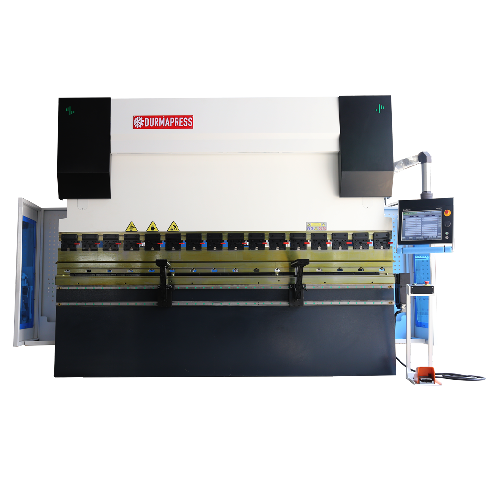
CNC Press Brake DA66T
General Features
DA66T electro-hydraulic CNC Press Brake Machine
- Sturdy steel plate welded structure, vibration relieve stress
- Stable and reliable upper transmission
- Outstanding eccentric load function, the sheet is allowed to bend at any point of the lower die, not necessarily in the middle
- Electro-hydraulic proportional servo synchronization to ensure the accuracy of repeated operations
- It can be controlled at any point within the stroke, with repeatability up to +/-0.01 and parallelism up to 0.02
- Lower worktable adopts deflection compensation or upper die is equipped with deflection compensation mechanism
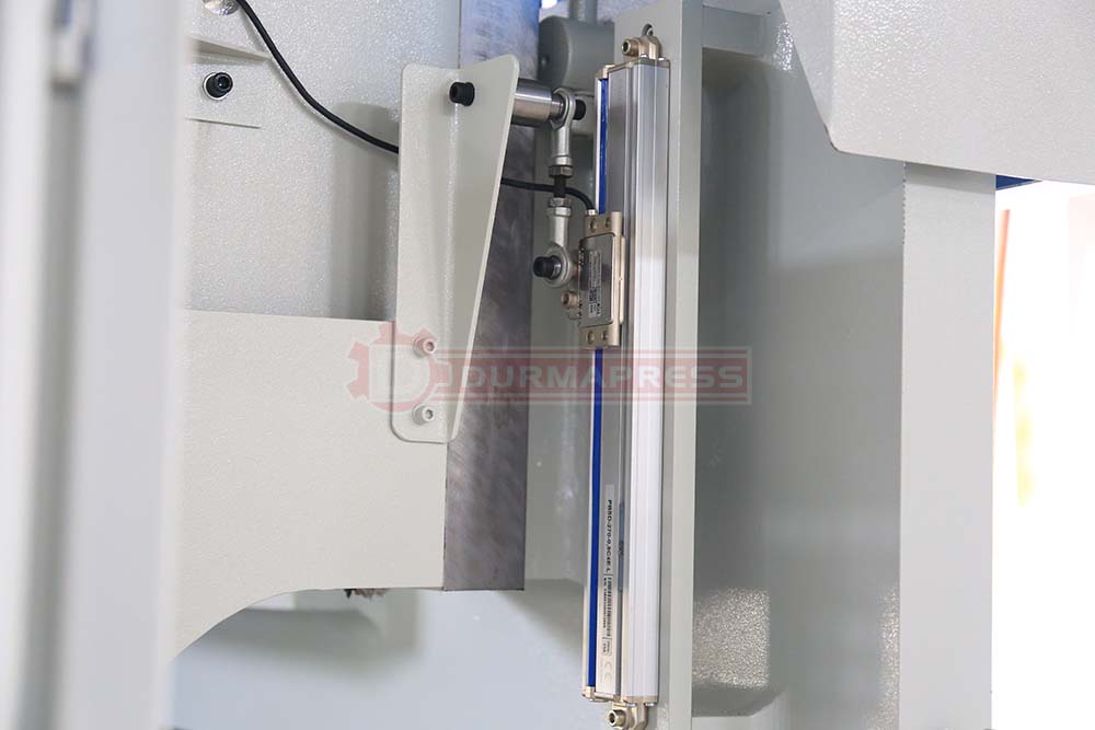
- Equipped with Dutch Delem DA66T CNC system, grating ruler, Rexroth hydraulic system valve group, servo motor, and other well-known brand accessories, with good performance
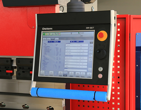
DA66T CNC Controller From Delem
Controller Data
- 2D graphical touch screen programming mode
- 3D visualisation in simulation and production
- 17″ high resolution colour TFT
- Full Windows application suite
- Delem Modusys compatibility (module scalability and adaptivity)
- USB, peripheral interfacing
- User specific application support within the controllers multitasking environment
- Sensor bending & correction interface
- Profile-TL offline software
Inquiry Now For Agent Price
Machine Frame
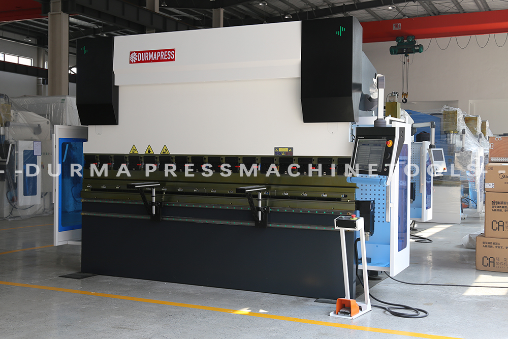
The DA66T electro-hydraulic CNC Press Brake machine model is MB8 Series CNC Press Brake with a solid steel plate welded structure, vibration-relief stress; outstanding eccentric load function, sheet metal is allowed to bend at any point of the lower die, It does not have to be in the middle; the electronic hydraulic proportional servo is synchronized to ensure the accuracy of repeated operations; it can be controlled at any point within the stroke, with a repeatability of +/-0.01 and a parallelism of 0.02.
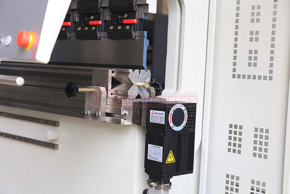
Press Brake Toolings
The standard top punch and dual-V bottom die are specially designed for bending sheet metals. More press brake toolings can be selected as per your practical use. Material and HRC47 degree values are marked on it
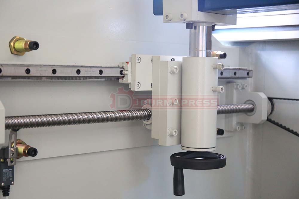
Back Guage
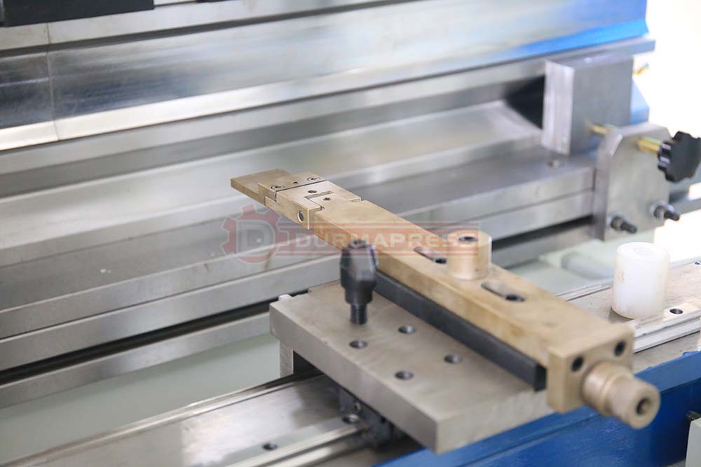
We using the Taiwan PMI ball screw and linear guide to ensure the moving of X-axis with higher accuracy than using rod. And the backgauge adopt timing belt & wheel mechanism which controlled by servo motor instead of step motor. The height of the backgauge finger can be adjusted manually. Totally there're THREE pcs of backgauge fingers for positioning.
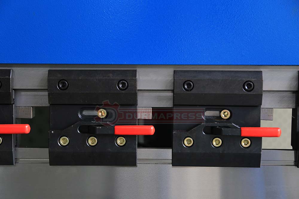
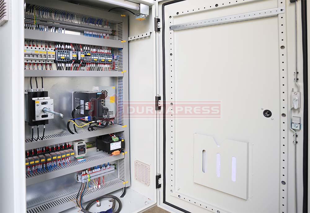
OTHER COMPONENTS

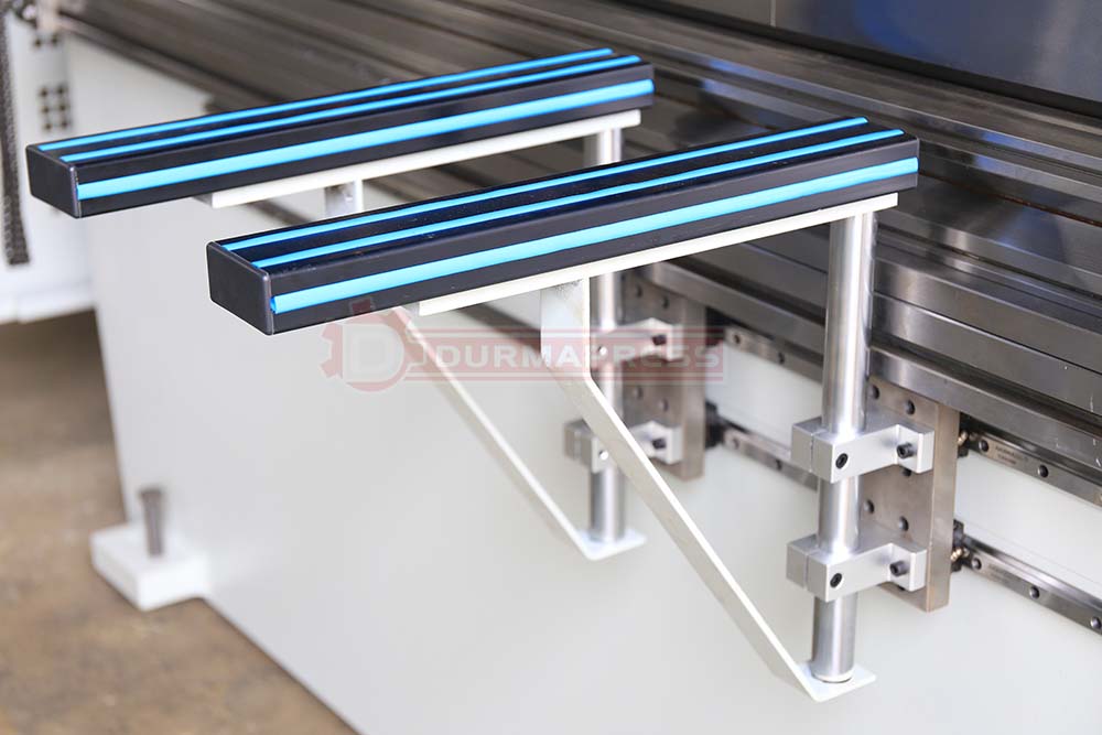
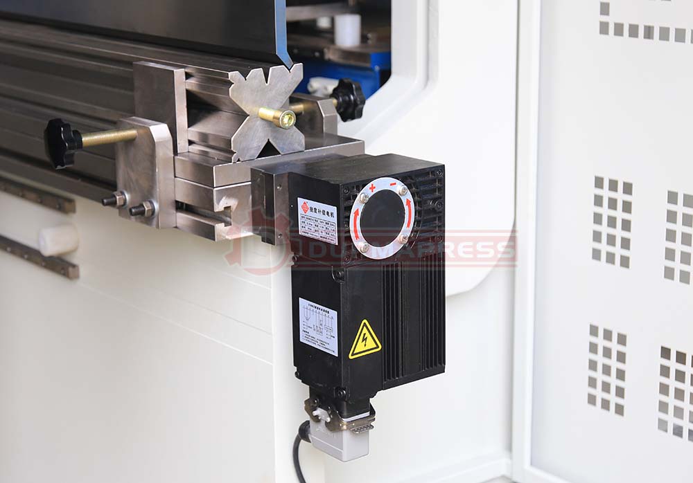
TECHNICAL DATA
| Seri-al NO. | Name | Numerical Value | Unit | |||||||||||||||||||||||||||||||||||||||||||||||||||||
|---|---|---|---|---|---|---|---|---|---|---|---|---|---|---|---|---|---|---|---|---|---|---|---|---|---|---|---|---|---|---|---|---|---|---|---|---|---|---|---|---|---|---|---|---|---|---|---|---|---|---|---|---|---|---|---|---|
| 40T/2500 | 63T/2500 | 63T/3200 | 63T/4000 | 80T/2500 | 80T/3200 | 80T/4000 | 100T/2500 | 100T/3200 | 100T/4000 | 125T/3200 | 125T/4000 | 160T/3200 | 160T/4000 | 200T/3200 | 200T/4000 | 250T/3200 | 250T/4000 | 300T/3200 | 300T/4000 | 300T/6000 | 400T/3200 | 400T/4000 | 400T/6000 | 500T/6000 | 600T/6000 | |||||||||||||||||||||||||||||||
| 1 | CNC Control Axis | 3+1 axis ( Y1, Y2, X + V Crowning ) Optional R axis | ||||||||||||||||||||||||||||||||||||||||||||||||||||||
| 2 | Nominal force | 4000 | 630 | 630 | 630 | 800 | 800 | 800 | 1000 | 1000 | 1000 | 1250 | 1250 | 1600 | 1600 | 2000 | 2000 | 2500 | 2500 | 3000 | 3000 | 3000 | 4000 | 4000 | 4000 | 5000 | 6000 | KN | ||||||||||||||||||||||||||||
| 3 | Bending length | 2500 | 2500 | 3200 | 4000 | 2500 | 3200 | 4000 | 2500 | 3200 | 4000 | 3200 | 4000 | 3200 | 4000 | 3200 | 4000 | 3200 | 4000 | 3200 | 4000 | 6000 | 3200 | 4000 | 6000 | 6000 | 6000 | mm | ||||||||||||||||||||||||||||
| 4 | Slider Stroke | 150 | 200 | 200 | 200 | 200 | 200 | 200 | 200 | 200 | 200 | 200 | 200 | 200 | 200 | 200 | 200 | 250 | 250 | 200 | 200 | 250 | 320 | 320 | 320 | 320 | 320 | mm | ||||||||||||||||||||||||||||
| 5 | Daylight | 430 | 470 | 470 | 470 | 470 | 470 | 470 | 470 | 470 | 460 | 470 | 470 | 470 | 460 | 470 | 470 | 470 | 470 | 500 | 500 | 540 | 560 | 560 | 560 | 560 | 560 | |||||||||||||||||||||||||||||
| 6 | Throat Depth | 250 | 400 | 400 | 400 | 400 | 400 | 400 | 400 | 400 | 400 | 400 | 400 | 400 | 400 | 400 | 400 | 520 | 520 | 280 | 280 | 400 | 400 | 400 | 400 | 470 | 500 | |||||||||||||||||||||||||||||
| 7 | Table width | 140 | 140 | 140 | 140 | 140 | 140 | 140 | 140 | 140 | 140 | 140 | 140 | 140 | 140 | 140 | 140 | 140 | 140 | 140 | 140 | 140 | 140 | 140 | 140 | 160 | 160 | |||||||||||||||||||||||||||||
| 8 | Working table height | 900 | 1000 | 1000 | 1000 | 1000 | 1000 | 1000 | 1000 | 1000 | 1000 | 1000 | 1000 | 1000 | 1000 | 1000 | 1000 | 1000 | 1000 | 1000 | 1000 | 1000 | 1000 | 3150 | 1000 | 1000 | 1000 | mm | ||||||||||||||||||||||||||||
| 9 | Working Speed | Full Load-speed | 130 | 130 | 130 | 130 | 130 | 130 | 130 | 130 | 130 | 130 | 130 | 130 | 130 | 120 | 130 | 120 | 110 | 110 | 150 | 150 | 90 | 85 | 85 | 85 | 85 | 85 | Mm/sec | |||||||||||||||||||||||||||
| Work-speed | 0-10 | 0-10 | 0-10 | 0-10 | 0-10 | 0-10 | 0-10 | 0-10 | 0-10 | 0-10 | 0-10 | 0-10 | 0-10 | 9 | 9 | 9 | 9 | 9 | 0-9.5 | 0-9.5 | 9 | 8.5 | 8.5 | 8.5 | 8.5 | 8.5 | ||||||||||||||||||||||||||||||
| High-return speed | 110 | 110 | 110 | 110 | 110 | 110 | 110 | 110 | 110 | 110 | 110 | 110 | 110 | 95 | 95 | 95 | 95 | 95 | 110 | 110 | 100 | 85 | 85 | 85 | 75 | 85 | ||||||||||||||||||||||||||||||
| 10 | CNC Backguage | Max Travel X- Axis | 400 | 500 | 500 | 500 | 500 | 500 | 500 | 500 | 500 | 500 | 800 | 800 | 800 | 800 | 800 | 800 | 800 | 800 | 500 | 500 | 800 | 550 | 550 | 550 | 550 | 550 | MM | |||||||||||||||||||||||||||
| Max Travel R- Axis | 200 | 200 | 200 | 200 | 200 | 200 | 200 | 200 | 200 | 200 | 200 | 200 | 200 | 200 | 200 | 200 | 200 | 200 | 150 | 150 | 200 | 150 | 150 | 150 | 150 | 150 | MM | |||||||||||||||||||||||||||||
| Finger Block | 2 | 3 | 3 | 3 | 3 | 3 | 3 | 3 | 3 | 3 | 3 | 3 | 3 | 3 | 3 | 3 | 3 | 3 | 3 | 3 | 3 | 3 | 4 | 6 | 6 | 6 | PC | |||||||||||||||||||||||||||||
| 11 | Capacity | Hydraulic pressure | 275 | 275 | 275 | 275 | 275 | 275 | 275 | 275 | 275 | 275 | 275 | 275 | 275 | 275 | 275 | 275 | 275 | 275 | 275 | 275 | 275 | 275 | 275 | 275 | 275 | 275 | Bar | |||||||||||||||||||||||||||
| Motor Power | 5.5 | 5.5 | 7.5 | 5.5 | 7.5 | 7.5 | 7.5 | 7.5 | 7.5 | 7.5 | 7.5 | 7.5 | 11 | 11 | 15 | 15 | 18.5 | 18.5 | 22 | 22 | 22 | 30 | 30 | 30 | 37 | 45 | Kw | |||||||||||||||||||||||||||||
| Oil Tank Capacity | 200 | 300 | 300 | 300 | 300 | 300 | 300 | 300 | 300 | 300 | 300 | 300 | 300 | 300 | 300 | 300 | 300 | 300 | 300 | 300 | 300 | 300 | 300 | 300 | 300 | 300 | Lts | |||||||||||||||||||||||||||||
| 12 | Machine weight | 2300 | 4800 | 5400 | 6200 | 5800 | 6300 | 7800 | 8500 | 8500 | 9600 | 8800 | 9800 | 10200 | 10500 | 14000 | 15000 | 15500 | 16500 | 16800 | 17800 | 24500 | 23000 | 26500 | 32500 | 40000 | 6550 | Kgs | ||||||||||||||||||||||||||||
| 13 | Overall dimension | Length | 2850 | 4550 | 4550 | 4550 | 2850 | 3550 | 4550 | 2850 | 3650 | 4550 | 3850 | 4550 | 3550 | 4550 | 3550 | 4360 | 4350 | 4350 | 3550 | 4550 | 6350 | 3850 | 4550 | 6550 | 6550 | 2350 | mm | |||||||||||||||||||||||||||
| Width | 1860 | 1950 | 1950 | 1950 | 2250 | 2250 | 2250 | 2250 | 2250 | 2250 | 2250 | 2250 | 2250 | 2250 | 2250 | 2250 | 2250 | 2250 | 2250 | 2250 | 2250 | 2250 | 2250 | 2250 | 2250 | 3580 | ||||||||||||||||||||||||||||||
| Height | 1900 | 2150 | 2150 | 2150 | 2250 | 2250 | 2250 | 2450 | 2450 | 2450 | 2480 | 2480 | 2680 | 2680 | 2880 | 2880 | 2980 | 2980 | 3180 | 3180 | 3200 | 3180 | 3180 | 3180 | 3380 | |||||||||||||||||||||||||||||||
| 14 | Power requirement | AC 220V~480V,3ph,50/60HZ | ||||||||||||||||||||||||||||||||||||||||||||||||||||||
